User's Guide
Overview
Terminology
Design vs Project
It is important to understand Designs and Projects, and how they differ from each other.
Design
A Design describes a model of an instrument, such as Dreadnought, OM, or L-00. A Design includes:
- Shape of the instrument
- Arches (if any)
- Bracing patterns
- Fretboard
One Design can be used in multiple Projects.
When you add a custom Design, it will be based on one of:
- A built-in stock design (such as Dreadnought, OM, etc.)
- A custom design that you have previously created
See also:
Project
A Project is a specific instrument that you are making. If you are building two identical instruments, one for Sally and one for Alan, there will be a separate Project for each. A Project includes:
- A design
- Chladni pattern photos
- Spectrum analyzer samples
- Notes
See also:
Demo Project and Demo Design
Luthier Lab includes a starter project called Demo Project,
which uses a design called Demo Design. Demo Project (and
Demo Design) can be used to experiment with the Luthier Lab tools. You
can think of it as a “sandbox” or “scratch” area.
When you are ready to create your own project, see Adding a Project.
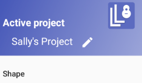
Active Project
The active project is the currently selected project. Any changes you make will
be stored in that project. The first time you run Luthier Lab, the active project will be the
project named Demo Project. 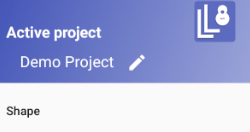
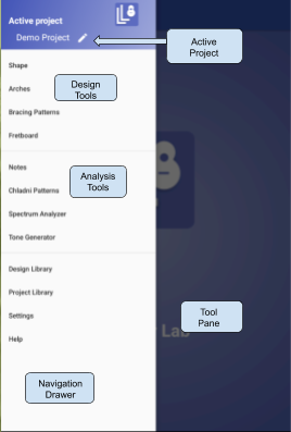
The active project is shown at the top of the Navigation Drawer.
See also:
Stock Design vs Custom Design
Luthier Lab has a library of 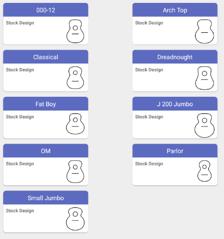 stock designs (for example: Classical, Dreadnought, OM, etc)
that you can use as the starting point for your custom designs.
stock designs (for example: Classical, Dreadnought, OM, etc)
that you can use as the starting point for your custom designs.
Stock designs cannot be edited. When you make a new (custom) design based on a stock design, a copy will be made of the stock design, and your edits will be applied to that copy.
Design Tools
Shape
Design the shape of an instrument, in terms of lines and arcs.
See: Shape
Arches
Create a topological map of the top and back of an instrument, representing the arching pattern for arch top instruments. Allows for different arches for top and back.
See: Arches
Bracing Pattern
Create the bracing for an instrument. You can draw individual braces as well as load in patterns from a library of stock bracing patterns. Allows for different bracing patterns for top and back.
See: Bracing Patterns
Fretboard
Design the fretboard of an instrument. Calculates the fret positions and saddle compensation. Allows for dual scale.
See: Fretboard
Analysis Tools
Notes
For taking notes about a specific instrument. Supports text notes and contact info notes.
See: Notes
Chladni Patterns
For storing photos of your Chladni patterns. The photos are stored in albums labeled with the tone generator frequency. You can create multiple albums, associated with different phases of your analysis process. (Used in conjunction with the Tone Generator.)
See: Chladni Patterns
Spectrum Analyzer
Captures a sample of the sound from an instrument, and graphs the frequency of the sound sample. The graph can be annotated to mark peak frequencies. Each sample is stored for later reference.
See: Spectrum Analyzer
Tone Generator
An audio frequency tone generator that supports various waveforms. Can generate constant tone or sweep tone.
See: Tone Generator
Design Library
For managing your Designs (instrument models such as Dreadnought, OM, or L-00). Provides a library of stock designs, and the ability to create custom designs. Designs can be shared with other Luthier Lab users, via import/export.
See also: Design vs Project
Project Library
For managing your Projects (specific instruments you are making). Projects can be shared with other Luthier Lab users, via import/export.
See also:
Settings
For setting Luthier Lab options.
See also: Settings
Navigation Drawer
The navigation drawer is used to select the active project, and to access the tools.
Select the Navigation Drawer icon ( ![]() ) to raise the Navigation Drawer. This icon is visible in all of the tools. You do not have
to leave a tool to raise the Navigation Drawer and go to another tool.
) to raise the Navigation Drawer. This icon is visible in all of the tools. You do not have
to leave a tool to raise the Navigation Drawer and go to another tool.
Active Project
The active project is the currently selected project. Any changes you make will be stored in that project. The first time you run Luthier Lab, the active project will be the project named Demo Project.
The active project is shown at the top of the Navigation Drawer.
Changing the Active Project
You can change the active project by pressing the edit icon
(![]() )
next to the project name (at the top of the Navigation Drawer).
)
next to the project name (at the top of the Navigation Drawer).
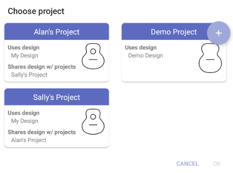
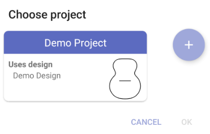
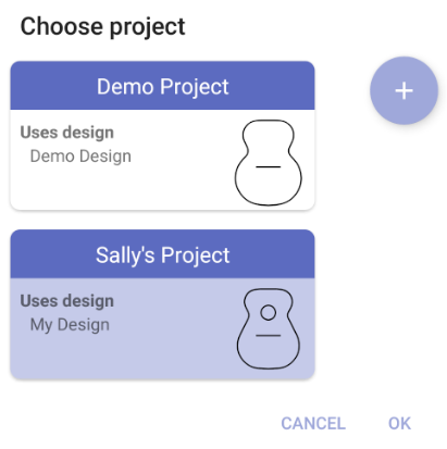
The Choose project dialog will be displayed, with a list of
your projects. You can select one of those projects, or press the
plus sign icon
( )
to create a new project.
)
to create a new project.
In this example there are three projects. You can see that Alan's Project and Sally's Project share a design (My Design). The Demo Project uses design Demo Design, which is not shared with any other projects.
Adding a Project
When you are ready to create your own Project (corresponding to an instrument you are making):
- Press the edit icon
(
 )
next to the project name (at the top of the
Navigation Drawer). The
Choose project dialog will be displayed:
)
next to the project name (at the top of the
Navigation Drawer). The
Choose project dialog will be displayed:
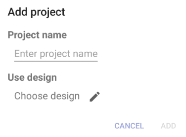
- Press the plus sign icon
(
).
The
Add project dialog will be displayed:
- Enter a name for your project, for example:
Sally's Project.
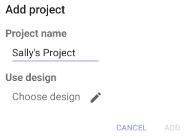
- Press the edit icon
(
).
The
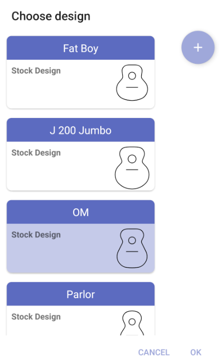
Choose design dialog will be displayed, showing all of the stock
designs and any custom designs you have previously created.
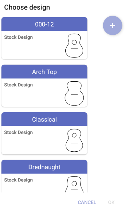
- Scroll through the designs and select the one you want. For example:
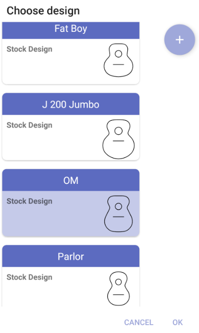
- Press
to select this design. Luthier Lab will create
a new design based on the selected design (in this case: the OM design).
By default the new design's name will be based on the project name (in this
case: Sally's Project's Design). You can use the default name, or choose your
own name, for example:
My Design.
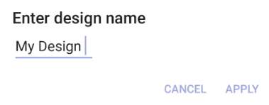
- Press
to choose the design name. The
Add project dialog will be displayed again, showing the project name and design you have selected.
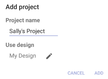
- Press
to create the new project, and add it to your Project
Library. The
Choose project dialog will be displayed again, with your
newly-added project selected.
- Press
to select your new project. At the top of the Navigation
Drawer you will now see your new project as the
Active project. The tools will
now operate in the context of the new project (your data will be saved in the
new project).
Design Tools
Design Options
These options (in the options menu ![]() ),
can be set in any of the design tools, and apply to all of the design tools.
),
can be set in any of the design tools, and apply to all of the design tools.
- Metric: Controls whether metric or imperial units are used
- Left handed: If this switch is on the instrument shape will be left-handed (the image of the instrument will be flipped)
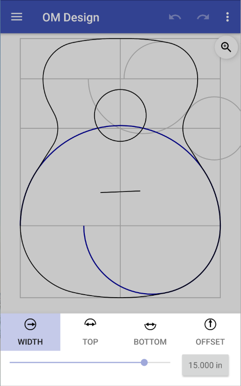
Shape
The Shape tool is for adjusting the shape of the instrument. Instrument shapes in Luthier Lab are defined in terms of these components:
- Length of the body
- Lower bout circle
- Waist circle
- Upper bout circle
- Sound hole
- Neck flat
The components can be selected/de-selected by pressing on the instrument shape.
The Undo/Redo buttons (![]() )
allow you to step "back" and "forth" through your edits. When you exit
the Shape tool, the undo/redo history is lost.
)
allow you to step "back" and "forth" through your edits. When you exit
the Shape tool, the undo/redo history is lost.
The Undo all
option (in the menu
![]() ) reverts the shape to its starting state (before your
latest group of edits.
) reverts the shape to its starting state (before your
latest group of edits.
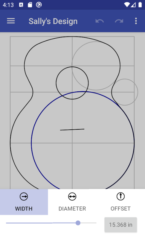
Component Controls
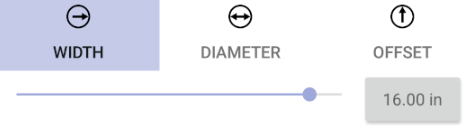
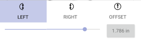
The components are adjusted using a shape component control. Pressing on a component will show the control for adjusting that component. The control will appear at the bottom of the screen. In the example above, the control for the lower circle is shown.
The control has a tab for each attribute that can be adjusted (in this example: width, diameter, and offset). Each tab has a slider for adjusting the value of the attribute (in this example: width). You can see the change in the shape as you adjust the value. If you prefer, you can enter an exact value by pressing on the "value button" next to the slider.
Dismiss the component control by pressing the back button or pressing anywhere on the shape.
Length and neck flat
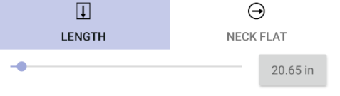
Pressing on the instrument outside of any of the circles will display the control for adjusting the length and the neck flat.
| Length | Length of body |
| Neck Flat | Flat area at neck join (optional) |
Sound hole
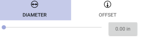
Pressing on the sound hole circle will show its control:
| Diameter | Sound hole's diameter |
| Offset | Distance from neck join to center of sound hole |
Circles
Pressing on each of the circles (lower bout, waist, upper bout) will show the circle control:
| Control | Lower Bout | Waist | Upper Bout |
|---|---|---|---|
| Width | Width of instrument at lower bout | Width of instrument at waist | Width of instrument at upper bout |
| Diameter | Lower bout circle's diameter | Waist circle's diameter | Upper bout circle's diameter |
| Offset | Distance from bottom of lower bout circle to tail of body | Distance from bottom of waist circle to tail of body | Distance from top of upper bout circle to neck join |
Split Circles
While many guitar shapes can be described using three circles and the lines connecting them, there are several popular designs (such as OM), where more control is needed.
The Split circles option (in the menu ![]() )
splits each circle into two half circles. You can independently control the
diameter of the top and bottom halves of the circles.
)
splits each circle into two half circles. You can independently control the
diameter of the top and bottom halves of the circles.
Pressing on each of the circles (lower bout, waist, upper bout) will show the split-circle control:
| Control | Lower Bout | Waist | Upper Bout |
|---|---|---|---|
| Width | Width of instrument at lower bout | Width of instrument at waist | Width of instrument at upper bout |
| Top | Lower bout circle's top diameter | Waist circle's top diameter | Upper bout circle's top diameter |
| Bottom | Lower bout circle's bottom diameter | Waist circle's bottom diameter | Upper bout circle's bottom diameter |
| Offset | Distance from bottom of lower bout circle to tail of body | Distance from bottom of waist circle to tail of body | Distance from top of upper bout circle to neck join |
Cutaways
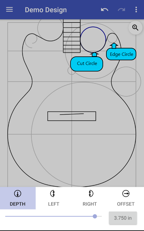
An instrument can have a single cutaway (on the treble side), or double cutaways (on treble and bass sides). The bass cutaway can mirror the treble cutaway, or be independent of the treble cutaway.
The Cutaway option
(in the menu ![]() )
enables the treble cutaway. When the treble cutaway is enabled, you can add a bass cutaway.
To get a mirror image bass cutaway, select the Symmetrical cutaway option.
To get an independent bass cutaway, select the Bass cutaway option.
)
enables the treble cutaway. When the treble cutaway is enabled, you can add a bass cutaway.
To get a mirror image bass cutaway, select the Symmetrical cutaway option.
To get an independent bass cutaway, select the Bass cutaway option.
Each cutaway is defined by two circles:
- Cut circle - depth and width of material to be removed
- Edge Circle - offset and width of remaining material
Pressing on either the Cut circle or the Edge circle will show its control. (In this example, the Split circle option is turned on, so the controls allow you to specify the diameter of the left and right halves of the circles.)
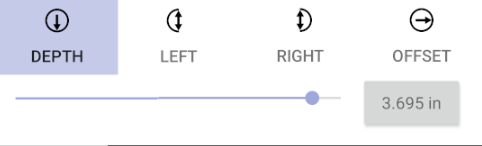
| Control | Cut | Edge |
|---|---|---|
| Depth | Depth of the cutaway from the neck join | N/A |
| Left | Left cut cutaway diameter | Left edge cutaway diameter |
| Right | Right cut cutaway diameter | Right edge cutaway diameter |
| Offset | Distance from the centerline to the side of the cut | Distance from the neck join to body perimeter. |
Scale Shape
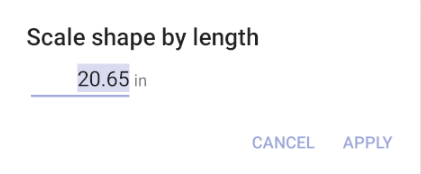
Sometimes an existing shape is close to the desired shape, but the size is wrong. For example, you might want to make a ukulele based on an OM.
You can scale the shape by selecting the Scale shape option from the menu
(![]() ).
Enter the desired length for the shape, and all other values for the shape
will be scaled proportionally.
).
Enter the desired length for the shape, and all other values for the shape
will be scaled proportionally.
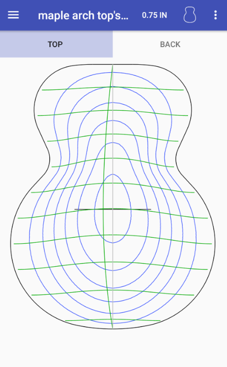
Arches
The Arches tool generates the arch curves for arch top instruments. The arch curves are calculated automatically using the bridge position, the shape of the instrument, and the height of the arch at the bridge.
The arch across the width of the instrument is a Curtate Cycloid. This pleasing curve is found on many old violins. It works well for guitars and mandolins also. See Curtate Cycloid.
The curve along the length of the instrument is a spline with the peak of the spline at the saddle position.
There are tabs at the top of the Arches display for selecting the top or back of the instrument.
Arch Height
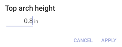
The arch height is displayed in the action bar at the top of the screen. In this example, the top’s arch height is set to 0.75”.
Pressing the value (0.75 IN) displays a dialog for changing the height. In this example, the arch height will be changed to 0.8”.
Contour Lines
Press the contour icon
(![]() ) (or select the Contour option in the menu) to show/hide a topological map of the arch.
) (or select the Contour option in the menu) to show/hide a topological map of the arch.
Contour Interval
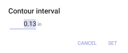
Select Contour interval in the menu (![]() )
to adjust the vertical distance
between contour lines. A smaller interval will display more contour lines.
)
to adjust the vertical distance
between contour lines. A smaller interval will display more contour lines.
Share/Export CAD Model
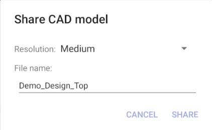
Select Share/Export CAD model in the menu (![]() )
to export the top or back arches, so you can import them into a CAD tool. The file
format is STL, which is accepted by most CAD tools.
)
to export the top or back arches, so you can import them into a CAD tool. The file
format is STL, which is accepted by most CAD tools.
Your device will give you the option to share the file to Google Drive or your email tool. Either option works, but some email servers limit the size of attachments.
Resolution
The arches are rendered as a sequence of triangles. The resolution of the model can be Coarse, Medium, or Fine. Coarse is roughly 600 triangles. Medium is roughly 5,000 triangles. Fine is roughly 18,000 triangles (file size ~3 Megabytes).
The finer the model, the less sanding will be needed on the top/back when it comes off of the CNC machine. Some CAD packages limit the number of triangles in an STL file to less than 10,000.
CAD Tools
Luthier Lab's STL output has been tested on the following CAD tools, as well as several other STL reader programs. If you have difficulty importing Luthier Lab's STL data into your CAD program, please contact us.
- BobCAD V24
- Fusion 360
- Onshape
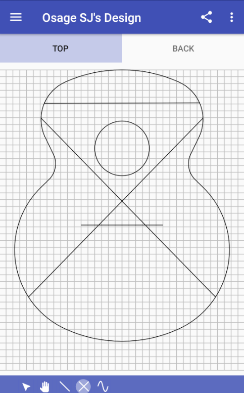
Bracing Patterns
The Bracing Pattern tool is for laying out a bracing pattern for a design. It has controls for selecting individual braces, adjusting individual braces, and drawing straight, symmetrical, and curved braces.
A collection of stock bracing patterns is provided, and can be used as a starting point for your custom bracing pattern.
There are tabs at the top of the Bracing Patterns display for selecting the top or back of the instrument.

Edit Controls
There are five controls for editing bracing patterns. Two of them are for manipulating existing braces and three are for drawing new braces.
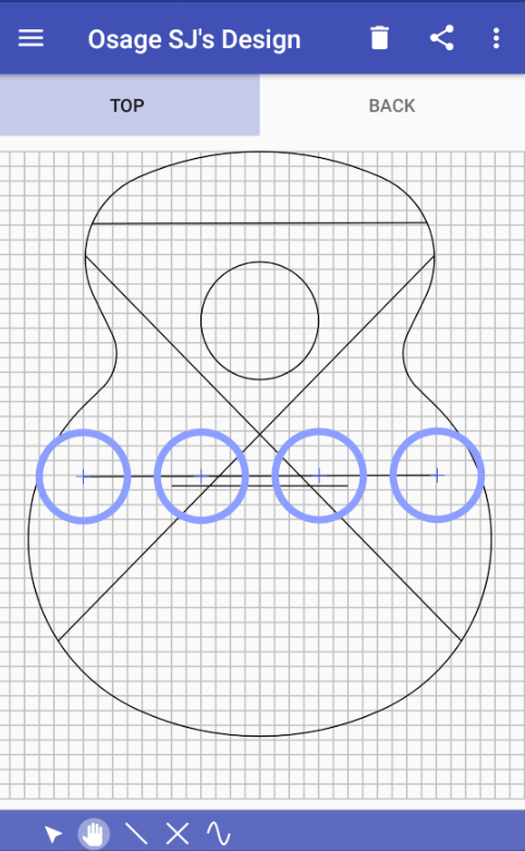
Manipulating Braces
Selection Mode
Press on the select button
(![]() )
to enter selection mode. Now press on the brace to be manipulated.
The control points for the brace are highlighted with large circles
and the editor automatically switches to manipulation mode.
)
to enter selection mode. Now press on the brace to be manipulated.
The control points for the brace are highlighted with large circles
and the editor automatically switches to manipulation mode.
Press anywhere near a straight or symmetrical brace to select it. Because of the complexity of a curved brace, press near the end point of the brace to selected it.
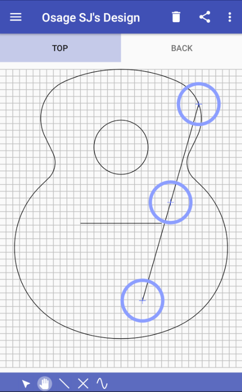
Manipulation Mode
Press on the manipulate button
(![]() )
to enter manipulation mode. You may press anywhere within the circle
to adjust the control point of the brace. Drag the control point to the
desired position.
)
to enter manipulation mode. You may press anywhere within the circle
to adjust the control point of the brace. Drag the control point to the
desired position.
The circles at the ends of the straight and symmetrical braces will move the end point. The control circle at the center of the straight brace will move the whole brace. The control circle at the center of the symmetrical brace will move only vertically.
Drawing Braces
Straight Brace
Use the straight brace button
(![]() )
to draw a straight brace. Press anywhere on the shape to start a
straight brace and drag to the end position of the brace. If the start
or end of the brace is near the edge of the shape, the start or end
will snap to the shape.
)
to draw a straight brace. Press anywhere on the shape to start a
straight brace and drag to the end position of the brace. If the start
or end of the brace is near the edge of the shape, the start or end
will snap to the shape.
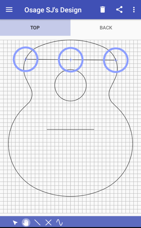
Symmetrical Brace
The symmetrical brace is actually two braces that are symmetrical along the centerline of the shape. This is useful for drawing X braces, A braces, and fan braces.
Use the symmetrical brace button
(![]() )
to draw a symmetrical brace. Press anywhere on the shape to start a
symmetrical brace and drag to the end position of the brace.
The complementary brace is automatically drawn.
)
to draw a symmetrical brace. Press anywhere on the shape to start a
symmetrical brace and drag to the end position of the brace.
The complementary brace is automatically drawn.
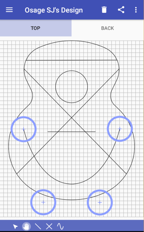
Curved Brace
Some designs use curved braces. Curved braces are drawn using cubic splines. The cubic spline is defined by two end points and two control points.
Press the curved brace button
(![]() )
to draw a curved brace. Press anywhere on the shape to start the curved
brace and drag to the end position of the brace. A straight line is drawn
between the start and end points of the brace.
)
to draw a curved brace. Press anywhere on the shape to start the curved
brace and drag to the end position of the brace. A straight line is drawn
between the start and end points of the brace.
The curved brace is automatically selected after it is drawn. Press inside the endpoint circles to move the end points. The two control circles are also shown. Press inside the control point circles to adjust the curved line. The line does not necessarily pass through the control points.
A smooth curve is drawn based on the position of the end points and the control points. It takes practice manipulating the control points to get the shape of the curved brace to the desired position
Menu Options
Delete Brace
When a brace is selected, the delete icon
(![]() )
is displayed on the action bar. Press the delete icon to delete the selected brace.
)
is displayed on the action bar. Press the delete icon to delete the selected brace.
Delete All
Deletes all of the braces.
Choose Stock Pattern
Allows you to use a stock bracing pattern as a starting point for your custom bracing pattern. The selected brace pattern is added to the existing design. It does not replace any existing braces.
Grid
Displays a grid on the screen. The grid squares are ½ inch when using Imperial units, and 1 cm when using metric units. See also: Settings: Show grid.
Snap to Brace
Enables a feature where the endpoints of braces snap to a nearby brace. This works when the editor is in manipulation mode. See also: Settings: Snap to brace.
Stock Bracing Patterns
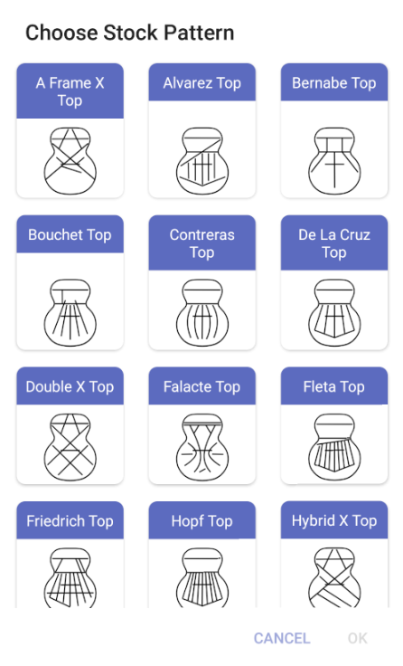
It is often more convenient to load a stock bracing pattern into a design and then edit it to fit the shape, or otherwise alter the pattern.
There are over 30 stock bracing patterns provided. Many of these patterns were drawn on the classical shape but some are for steel string guitars and are drawn on the Small Jumbo shape.
Loading a stock pattern adds the braces of that pattern to any braces that already exist for that design. You can add two patterns from the stock bracing patterns and they will overlay each other. When this happens, it is usually easiest to delete all of the braces and start over.
Any custom bracing pattern that you create is also added to the stock bracing patterns under the name of the design.
Fretboard
This tool calculates the positions of the frets for a given scale length. It also displays an image of the fretboard. It uses the formula (1 - ( 1 / 2n/12)) * scale = fret number. This produces an equal tempered scale.
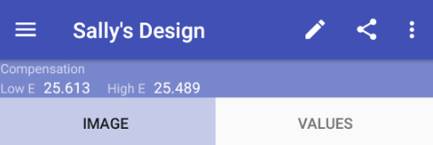
It is possible to specify two scale lengths; one for the treble string and the other for the bass string. The saddle compensation is calculated for steel string guitars. This compensation is based on the scale length. It does not take into account the string’s physical properties.
See also: Settings: Show saddle compensation
Fretboard Values
Press the edit icon
(![]() )
in the action bar to raise the Fretboard values dialog. This dialog lets you set
any of the attributes of the fretboard. Press in the data field for any of the
values to enter a new value for that field.
)
in the action bar to raise the Fretboard values dialog. This dialog lets you set
any of the attributes of the fretboard. Press in the data field for any of the
values to enter a new value for that field.
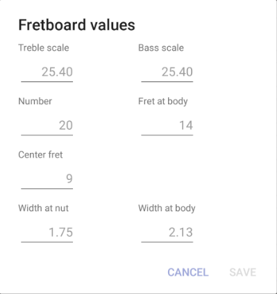
- Treble scale is the scale for the treble string. It is also the scale for the whole fretboard when the fretboard is single scale. Any value from 9.0" to 39.0" is allowed.
- Bass scale is the scale for the bass string. It is ignored when the fretboard is single scale. Any value from 9.0" to 39.0" is allowed.
- Number is the number of frets on the fretboard. Any value from 1 to 40 is allowed.
- Fret at body is the fret that is at the body of the instrument. Typically 12 or 14 but any value from 1 to 40 is allowed.
- Center fret is the fret that has the same offset for the bass and treble frets on dual scale instruments.
- Width at nut is the width of the fretboard at the nut.
- Width at body is the width of the fretboard at the body join.
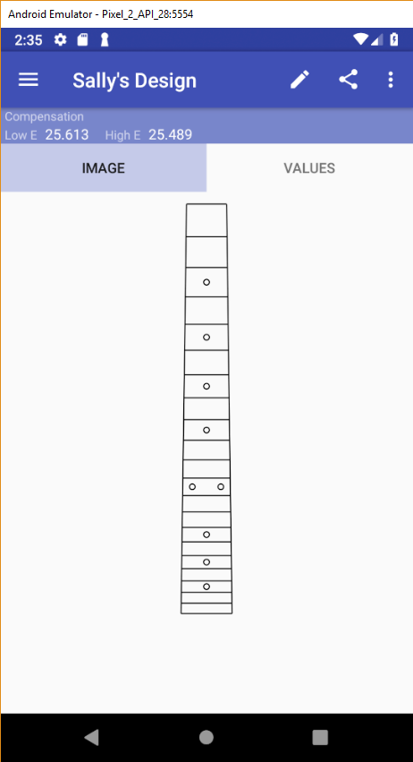
Image Tab
The Image tab shows an image of the fretboard.
Values Tab(s)
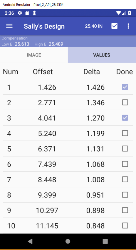
There can be one or two values tabs. If the fretboard is single scale there is one tab, named . If the fretboard is dual scale, there are two tabs: and .
In this example, the fretboard is not dual scale, so there is one tab.
Each values tab has four columns:
- Num: fret number, starting at the fret closest to the nut
- Offset: distance from the nut to the center of the fret
- Delta: distance from the center of the previous fret to the center of the fret
- Done: a checkbox that you can use to keep track of your progress through any of the fretting processes (such as slotting, leveling, dressing, etc).
Scale Length
The scale length is displayed in the action bar when one of the values tabs is displayed. In this example, the scale length is 25.40”.
To change the scale value, press on the scale length button.. The scale length can also be set in the Fretboard values dialog.Analysis Tools
Notes
During the development of a project, you may wish to record notes about that project. For example:
- The woods that are used in the project
- Special items that the customer requested
- A journal of the progress of the project
- Contact info for the customer
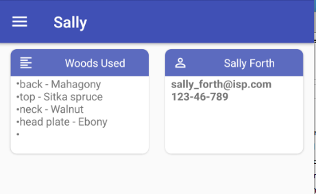
The Notes tool has a card display showing the notes for the project. Press on a card to open the note. If there are no notes, no cards will be shown.
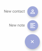
Press the Add button
()
to create a new note. This will expand to two other buttons for creating either a text note or a contact note.
Add Text Note
Press the New note button
( )
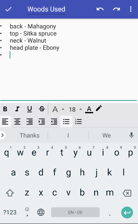
to create a new text note. This raises a text editor that allows you to enter
text. Common text formatting options are available.
)
to create a new text note. This raises a text editor that allows you to enter
text. Common text formatting options are available.
The title of the note is shown in the action bar at the top (in this example: Woods Used). Press the title’s text to create or change the title of the note.
Press in the text field to enter the text of the note. The editor options allow for formatting the text in the note.
The undo and redo buttons
(![]() )
undo and redo recent edits.
)
undo and redo recent edits.
Press the check button
(![]() )
to save the note and return to the Notes page. The notes page will display a card with
the title of the note and a snippet of the text in the note.
)
to save the note and return to the Notes page. The notes page will display a card with
the title of the note and a snippet of the text in the note.
Add Contact Note
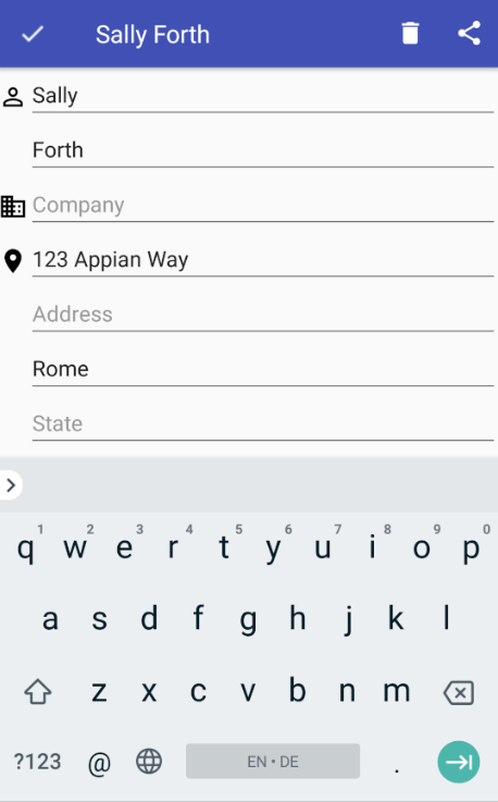
You can put customer contact information in a contact note. Press the New
contact button
( )
to create a new contact. Add any contact information to the contact note.
)
to create a new contact. Add any contact information to the contact note.
The first name and last name are combined to make the title of the contact note.
Press the check button
(![]() )
to save the contact note and return to the Notes page.
)
to save the contact note and return to the Notes page.
Tone Generator
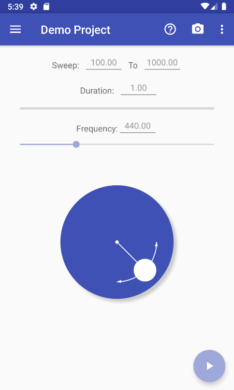
The Tone Generator is an audio frequency tone generator designed for use by luthiers. It supports multiple waveforms and a sweep function. It also has a button to start the device’s camera which is useful when generating Chladni patterns.
The tone comes out of the speaker of the device. Most phones and tablets are not loud enough. Connecting the device to an amplifier via the output jack or Bluetooth is usually necessary. It is recommended that a Bluetooth connection be used because there are no wires that can get in the way.
Start & Stop Tone
Press the action button at the bottom of the display to start
( )
or stop
(
)
or stop
( )
the tone generator.
)
the tone generator.
Adjust Frequency
The frequency of the tone can be adjusted in several ways:
-
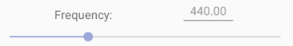 Frequency slider. Press the control indicator and slide to the left
or right to raise or lower the frequency.
Frequency slider. Press the control indicator and slide to the left
or right to raise or lower the frequency.
- Frequency value. Press the frequency value (in this example: 440.00) to set the frequency to a specific value.
-
 Spin Dial. The spin dial is used to gradually raise or lower the
frequency. This is useful when finding resonant frequencies on a sound board
or finished instrument.
Spin Dial. The spin dial is used to gradually raise or lower the
frequency. This is useful when finding resonant frequencies on a sound board
or finished instrument.
Press and hold on the white control indicator and move around the perimeter of the dial. Moving clockwise raises the frequency and counter-clockwise lowers the frequency.
Sweep
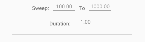
The tone generator will “sweep” the frequency from one value to another. This enables the Spectrum Analyzer to measure the resonant values across a particular range.
Press in the Sweep field or the To field to set the start and end
frequencies for the sweep. In this example the start is set to 500 and the end
is set to 2000. Press the sweep button
(![]() )
in the action bar to initiate the sweep. The start frequency can be either higher
or lower than the end frequency.
)
in the action bar to initiate the sweep. The start frequency can be either higher
or lower than the end frequency.
Press in the Duration field to set the duration of the sweep. The duration of the sweep can be as short as 0.1 seconds and as long as 120.0 seconds.
Camera
Press the camera button
(![]() )
in the action bar to start your device’s camera, to take a picture. This feature
is closely integrated with the Chladni Patterns tool. The picture
returned by the camera is placed in the open album in the Chladni Patterns
tool, and labeled with the current frequency of the Tone Generator.
)
in the action bar to start your device’s camera, to take a picture. This feature
is closely integrated with the Chladni Patterns tool. The picture
returned by the camera is placed in the open album in the Chladni Patterns
tool, and labeled with the current frequency of the Tone Generator.
Waveform
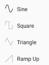
The form of the generated wave is controlled from the menu. The supported waveforms are:
- Sine
- Square
- Triangle
- Ramp Up
Chladni Patterns
The Chladni Patterns tool is an album management tool for images of Chladni patterns. It works closely with the Tone Generator tool. Each image taken with the device’s camera is labeled with the current frequency of the Tone Generator. If an image exists with a given frequency, the image is replaced.
You can take images from the Chladni Patterns tool or the Tone Generator tool. The images can be viewed from the Chladni Patterns tool.
Create Album for Untuned Top
When taking photos of Chladni patterns for a top or back, make sure that they are placed in an album for that top or back. To create an album, select Add album from the options menu. An Add album dialog will appear. Enter the name of the album. For example, Untuned Top. This will create the album.
Take a Photo
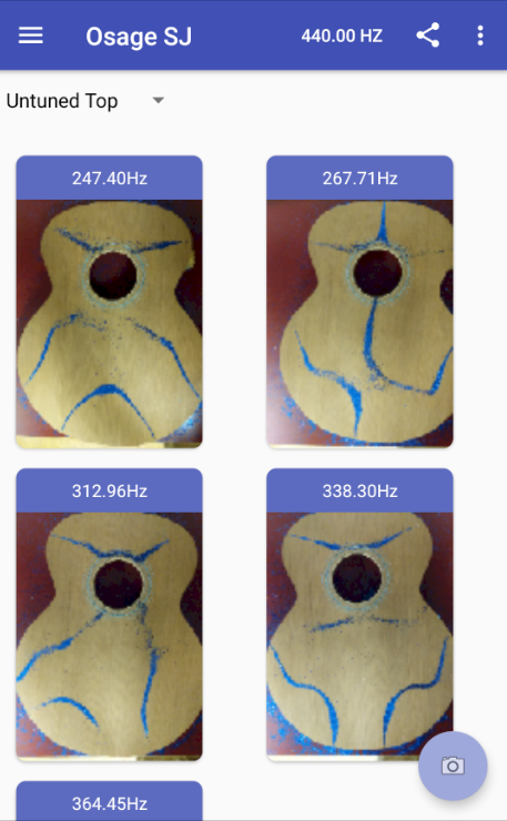
Suppose that you have used the Tone Generator to vibrate the untuned top and found a resonant frequency that forms a Chladni pattern.
- Press the camera button
(
 ).
Your default camera app will start.
).
Your default camera app will start.
- Take a picture of the pattern. The picture will be added to the Chladni Pattern album, and labeled with the tone generator frequency.
- Repeat these steps for each of the frequencies where the top displays a clear pattern.
Note the image labeled 338.30Hz. This is an interesting pattern and it is the pattern that you want to refer to when shaving the braces.
Create Album for Tuned Top
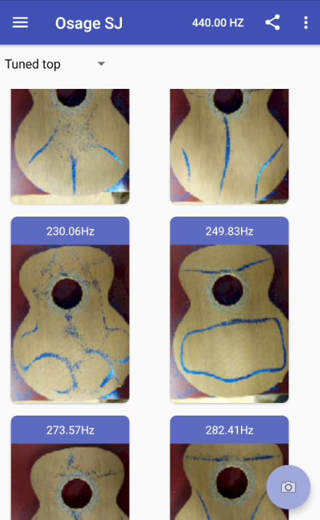
Use the Add album menu option to make an album for the tuned top. For this example, the new album is named Tuned top.
The pattern we saw at 338.30Hz was open at the corners. Shave the braces and find the new frequency that displays this pattern or one similar. The objective is to lower the frequency to between 245Hz and 260Hz and to close up the lower pattern so that it makes a ring. After several iterations of shaving and creating new patterns a new shape appears with the lower pattern making a ring and the frequency lowered.
At this point, work your way through the frequencies finding as many patterns as you can. Take a picture of each one. It will be saved in the new album.
Notice that the pattern that used to be at 338.30Hz is now at 249.83Hz and the lower portion of the pattern is now a closed ring. This is considered to be a tuned top.
Select Album to View
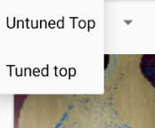
The current album's name is displayed in a drop down menu. Use the drop down to change the current album.
The current album is the album where new images will be added. This is true if the image is added from the Tone Generator tool as well.
Delete Image(s)
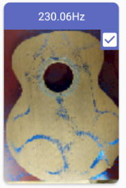
To delete an image, press on the image. A check box will appear in the upper right corner,
indicating that the image is selected. You may select more that one image. Press the image
again to un-select it. Press the delete icon
(![]() )
in the action bar to delete all of the selected images.
)
in the action bar to delete all of the selected images.
Rename Album
Use the drop down menu to select the album that you want to rename. Select the Rename album item from the option menu. A dialog will appear to enter the new name for the current album.
Delete Album
Use the drop down menu to select the album that you want to delete. Select the Delete album item from the option menu. A dialog will appear to confirm that you want to delete the album.
Change Tone Generator Frequency

It is sometimes convenient to change the frequency of the Tone Generator from the Chladni Pattern tool. The name of a new image is the current frequency but it will replace any existing image with the same name. If you want to take two images of the same Chladni pattern, you can change the current frequency by a small amount to make a unique name.
Press the current frequency in the action bar (in this example: 440.00 HZ). A dialog will appear to set the new frequency.
Spectrum Analyzer
The Spectrum Analyzer collects audio samples from the device’s microphone. It performs a Fast Fourier Transform (FFT) on the audio sample, and displays the frequency spectrum.
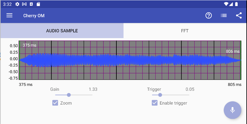
Audio Sample Tab
The audio sample tab displays the current sample. Samples are one second long. You can control the display with the control sliders and the boundary markers.
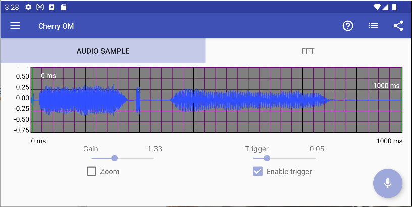
- Gain: Controls the amplitude of the signal. It can range from 0 to 10 times the sampled values.
- Trigger: Stop recording based on the amplitude of the input signal, see Trigger.
- Boundary Markers: Select a portion of the sample, see Boundary Markers.
- Zoom: Zoom the audio sample display to the selected portion, see Zoom.
Boundary Markers
Often a sample will contain extraneous sounds, or have two or more sounds that are of interest. The boundary markers allow you to select the portion of the audio sample that is analyzed by the spectrum analyzer.
The boundary markers are green vertical lines. Initially they are at the far left and far right of the audio sample display.
Selecting a Marker
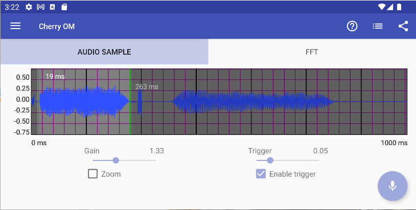
Press your finger near the lower or upper boundary marker. Drag the marker to a position at the beginning or end of a section of the sample that interests you. The selected marker will turn yellow while you drag it. The example shows that the first of several tones is selected. The remainder of the sample is grayed out.
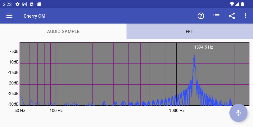
The FFT tab will display the frequency spectrum for the selected portion of the audio sample. In this example, the dominant frequency for the selected tone is 1394.5 Hz.

You can examine the third tone in the display by moving the boundary markers to select only the third tone.
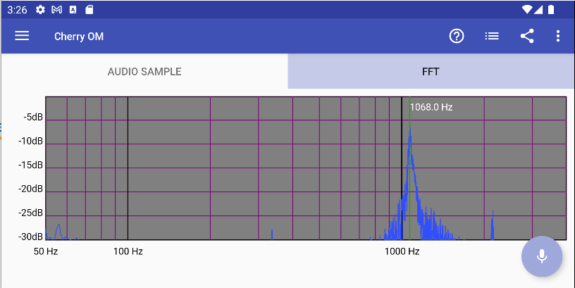
Now the FFT tab will display the frequency spectrum for the third tone. In this example, the dominant frequency for the third tone is 1068.0 Hz.
Zoom
The zoom toggle will "zoom" the audio sample display in to the elected by the boundary markers. Consider the multitone example. The third tone is selected.
This is the same audio sample with zoom enabled. It displays only the section that is selected (between the two boundary markers). The boundary markers are now at the far left and far right of the display. You can move the boundary markers into the display to further refine the selection. To select a portion of the sample greater than the current selection, you must disable zoom.
FFT Tab
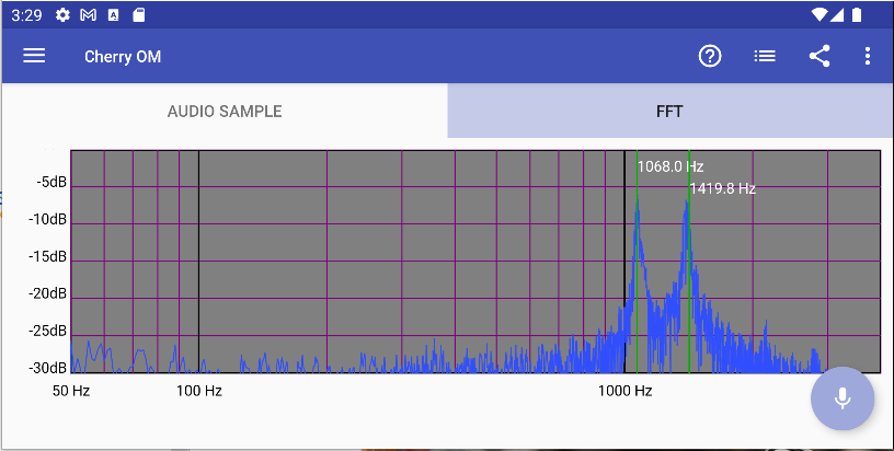
The FFT tab displays a Fast Fourier Transform of the sample displayed on the Audio Sample tab.
You can control the FFT display from the menu on the action bar.
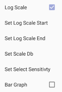
- Log Scale: Set the display frequency to be a log scale.
- Set Log Scale Start: Set the starting frequency of the log scale.
- Set Log Scale End: Set the ending frequency of the log scale.
- Set Scale Db: Set the lower Db of the scale to be displayed.
- Set Select Sensitivity: Set how close your finger has to be to an existing marker to select that marker.
- Bar Graph: Set the display to be a bar graph rather than a line graph.
Frequency Markers
It is often useful to mark peaks and valleys of the FFT graph with their frequency. You can place a frequency marker by pressing on the FFT display and sliding left or right until the green line is on the peak or valley. The green line will remain when you lift your finger. You can place as many frequency markers on a display as you wish.
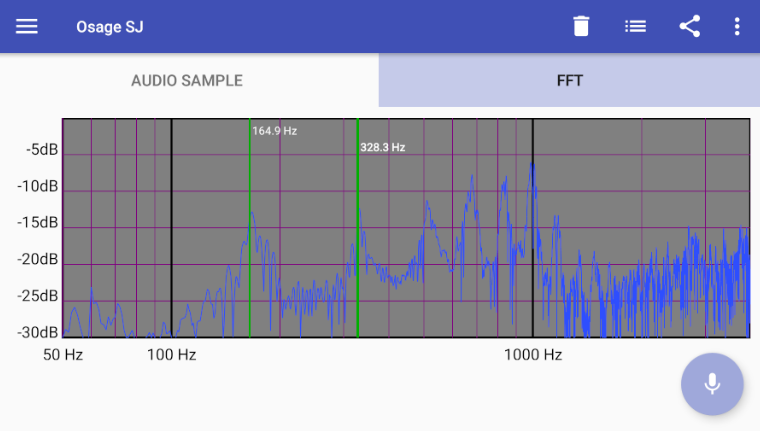
Selecting a Marker
If your finger is near an existing frequency marker when you lift it, the existing marker is selected and a new marker is not placed. A selected frequency marker is in bold letters (328.3 Hz in image above).
When a marker is selected, you can delete it by pressing the delete icon
(![]() )
in the action bar.
)
in the action bar.
You can’t move an existing frequency marker. You have to delete it and then place a new one.
Collect Audio Sample
Press the microphone on button
( )
to start recording audio. Press the microphone off button
(
)
to start recording audio. Press the microphone off button
( )
to stop recording audio. The sample will be the last second of audio prior to
turning off the microphone.
)
to stop recording audio. The sample will be the last second of audio prior to
turning off the microphone.
The most recent sample is displayed but previous samples are saved and can be viewed (see: Sample list).
Trigger
It can be very awkward to press the microphone on/off buttons while recording audio, especially when you have to pluck a string or tap on the instrument. The trigger function allows you to automatically stop recording, based on the amplitude of the input signal.
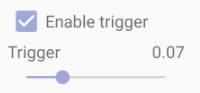
Press the Enable trigger checkbox to enable or disable triggering. The trigger value is a fraction of the maximum value the microphone picks up. A value of 0.01 will trigger on almost any sound level, and a value of 0.99 will trigger on only the loudest sounds.
When the trigger is disabled, recording will continue until you explicitly stop it. The audio sample will be the final second of the recording.
When the trigger is enabled, recording will stop when the input signal exceeds the trigger value. The audio sample will be the second after the input signal exceeds the trigger value.
Suppose you are doing an impulse excitation test
on an instrument. Set the trigger to a value that is above the ambient noise in the
room and press the microphone on button
().
Place the microphone in front of the instrument and tap on the bridge. The tap sound
should exceed the trigger threshold, and recording will continue for one second and
then stop. The sample will be displayed on the audio sample page. The audio sample
displayed in the image above is an example of such an impulse.
If recording stops too soon, raise the trigger value. If it doesn’t stop when the tap is done, lower the value.
Sample List
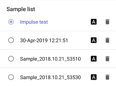
All samples taken for a given project are preserved and can be viewed. You select
which sample to view by pressing the sample list icon
(![]() )
in the action bar. This raises the sample list dialog, a scrolling list of all
of the samples. The current sample is highlighted. Select another sample to make
it the current one. To dismiss the dialog: press outside of the sample list or
use the back button.
)
in the action bar. This raises the sample list dialog, a scrolling list of all
of the samples. The current sample is highlighted. Select another sample to make
it the current one. To dismiss the dialog: press outside of the sample list or
use the back button.
The default name of each sample is the date and time that it was captured. You can
change the name of a sample by pressing the rename icon
(![]() ).
In the image above, the current sample has been renamed to “Impulse test”.
).
In the image above, the current sample has been renamed to “Impulse test”.
Press the delete icon
(![]() )
to delete a sample.
)
to delete a sample.
Impulse Excitation Technique (Bonk Test)
You can capture a “signature” of an instrument by performing the Bonk Test:
- Hang the instrument from the head stock, and dampen the strings.
- Start the Spectrum Analyzer recording, with a Trigger value above the ambient noise level in the room.
- Tap the saddle of the instrument with a small plastic head hammer
or a hard plastic ball suspended on a string, such that when it is released from a
constant distance from the instrument it strikes the saddle. (Bonk!)
The saddle of an instrument is hard enough that it won’t be damaged by the hammer or ball. Don’t strike the body of the instrument! The ball-on-a-string method gives a more consistent impulse.
The Spectrum Analyzer will store the sound generated by the bonk and the FFT tab will show the frequency spectrum.
Tapping the instrument in this way causes it to vibrate at all frequencies at once. The signal will be stronger at the resonant frequencies and weaker at frequencies that are not resonant. You can build up a library of bonk test results and notice that certain frequency spectrums will have characteristics that correspond with similar tonal qualities.
You can then shave some braces and do the experiment again to adjust the tone of the instrument. Which braces to shave to get a particular result depends entirely on the result you are trying to get and the experience you have with shaving braces.
Design Library
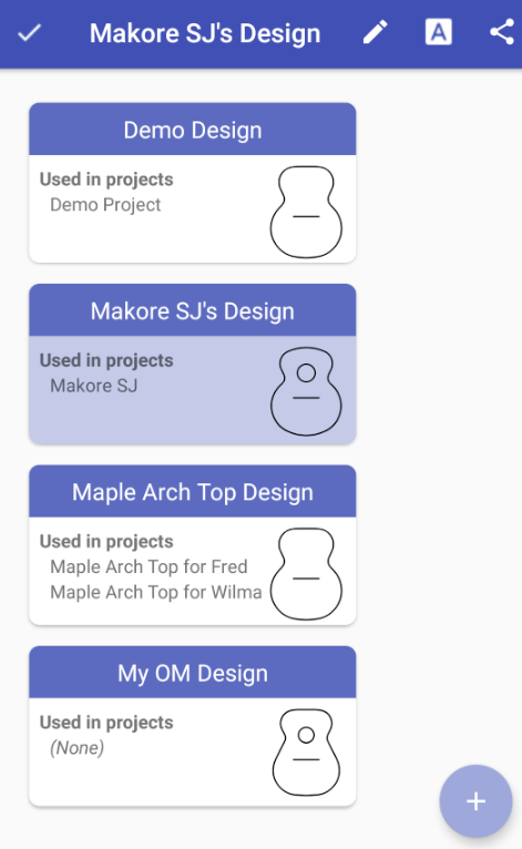
The Design Library shows all of the designs you have created (custom designs). There is a card for each design, showing the name of the design, a small image of the shape and a list of the projects that use the design (if any). (In this example, Maple Arch Top Design is used in two projects.)
To select a design, press on its card. The card’s background color will change to blue, to indicate that the design is selected. In this example the Makore SJ’s Design is selected.
Add Design
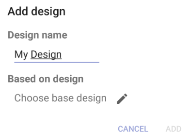
Press the Add
()
button to create a new custom design. The Add design dialog will appear. Enter
the name of your new design (in this example: My Design)
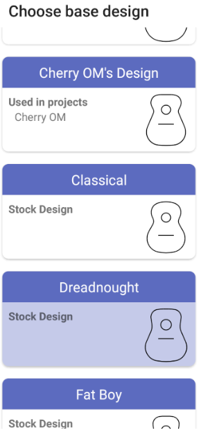
Every design must be based on an existing design. Press on the Choose base design icon
(![]() )
to select a base design, from either the stock designs or a custom design that you
created earlier. In this example, Dreadnought has been selected as the base design.
)
to select a base design, from either the stock designs or a custom design that you
created earlier. In this example, Dreadnought has been selected as the base design.
See also: Stock Design vs Custom Design
Rename Design
Press the rename icon
(![]() )
to rename the selected design.
)
to rename the selected design.
Delete Design
If the selected design is not used in any projects, it can be deleted.
Press the delete icon
(![]() )
to delete the selected design. A dialog will appear, to confirm that you want
to delete the design.
)
to delete the selected design. A dialog will appear, to confirm that you want
to delete the design.
Edit Design
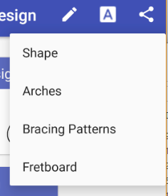
You can edit the selected design’s components (shape, arches, bracing patterns,
fretboard) by pressing on the edit icon
(![]() ).
This will raise a menu of the design tools. You can open any of the design tools to
edit that component of the design.
).
This will raise a menu of the design tools. You can open any of the design tools to
edit that component of the design.
Share/Export a Design
Press the share icon
(![]() )
to share the selected design. See Share/Export a Design/Project.
)
to share the selected design. See Share/Export a Design/Project.
Project Library
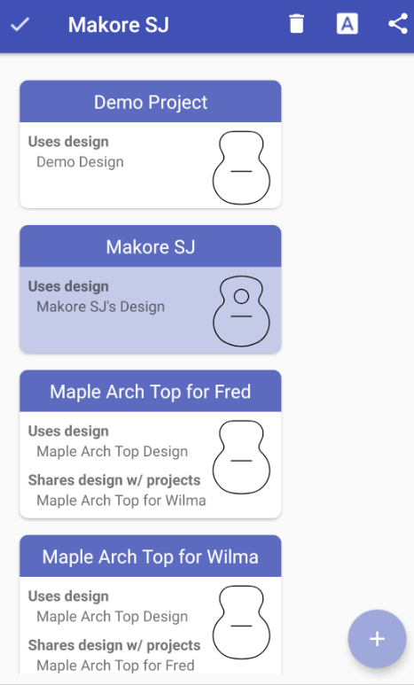
The Project Library shows all of your projects. There is a card for each project, showing the name of the project, the project’s design, a small image of the shape, and a list of other projects that share the design (if any). (In this example, Maple Arch Top for Fred and Maple Arch Top for Wilma share a design.)
To select a project, press on its card. The card’s background color will change to blue, to indicate that the design is selected. In this example Makore SJ is selected.
Add Project
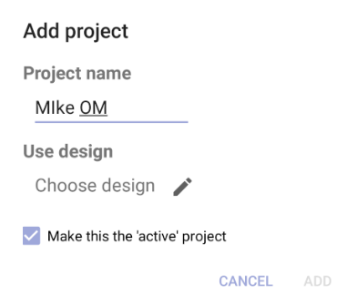
You can choose to set your new project as the active project
by using the Make this the 'active' project checkbox.
See also: Settings: Make new project 'active'
Press the Add button
()
to create a new project. The Add project dialog will appear.
Enter the project name (in this example: Mike OM) and choose a design by
pressing on the Choose design icon
(![]() ).
The Choose design dialog will appear showing a list of all the existing designs.
Select one of the designs and press OK.
).
The Choose design dialog will appear showing a list of all the existing designs.
Select one of the designs and press OK.
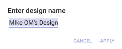
If you select a Stock Design (in this example: OM), a new custom design will be created based on the stock design. A dialog will appear for you to enter a name for the new custom design (in this example: Mike OM's Design).
Rename Project
Press the rename icon
(![]() )
to rename the selected project.
)
to rename the selected project.
Delete Project
Press the delete icon
(![]() )
to delete the selected project. A dialog will appear, to confirm that you want
to delete the project.
)
to delete the selected project. A dialog will appear, to confirm that you want
to delete the project.
If the project’s design is shared by another project, the design will not be deleted. Otherwise, it will be deleted along with the project.
Share/Export a Project
Press the share icon
(![]() )
to share the selected project. See Share/Export a Design/Project.
)
to share the selected project. See Share/Export a Design/Project.
Share/Export
Create a PDF File
You can create a PDF file for these tools:
- Shape
- Arches
- Bracing Patterns
- Fretboard
- Chladni Patterns
- Spectrum Analyzer
Press the Share icon
(![]() )
to create the PDF file. If the share icon is not visible on the action bar, it will
be in the menu
(
)
to create the PDF file. If the share icon is not visible on the action bar, it will
be in the menu
(![]() ).
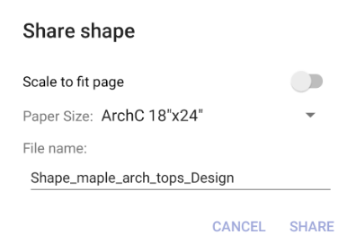
This raises the Share dialog. You can choose to scale the image to fit the page or
you can use a paper size that allows the shape to be drawn full size.
).
This raises the Share dialog. You can choose to scale the image to fit the page or
you can use a paper size that allows the shape to be drawn full size.

Press the button on the dialog to export the PDF file. The Send to dialog will ask you to select which app is to receive the file (the apps shown will depend on what apps you have installed on your device).
You can email the file (via Gmail or some other email tool), save it to a folder (for example: Google Drive), or send it to a printer (if you have a printer app installed).
Saving the file to a folder (like Google Drive) is often the easiest way to access the file later. You can take the file to your local copy center and have them print it on paper of the size you specified.
Export Notes
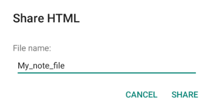
The Share/Export feature for Notes creates an HTML file of the note or contact.
Press the Share icon
(![]() )
to create the HTML file. If the share icon is not visible on the action bar, it will
be in the menu
(
)
to create the HTML file. If the share icon is not visible on the action bar, it will
be in the menu
(![]() ).
).
The file can be saved to a folder (for example: Google Drive), sent as an email, or opened in a browser.
Share/Export a Design/Project
The Share/Export feature for Designs and Projects provides a way to share a Design or Project with another Luthier Lab user.
When you share a Design/Project, an LLAB file will be created. If you provide this file to another Luthier Lab user, they can use it to import your Design/Project into their Luthier Lab data.
When a design or project is selected in the Design/Project Library, the
Share/Export icon
(![]() )
will be shown on the action bar. Pressing the icon will raise the Share design/project
dialog.
)
will be shown on the action bar. Pressing the icon will raise the Share design/project
dialog.
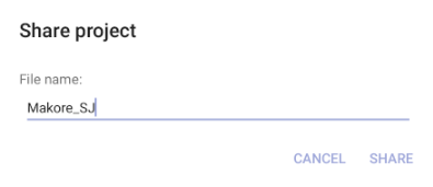
Press the button on the dialog to create the LLAB file. The Send to dialog will ask you to choose how to share the file. It can be saved to a folder (for example: Google Drive), or sent as an email.
When you share a project, the project’s design will also be shared. In this example, the project Makore_SJ, and its design (Makore_SJ’s Design) will be shared.
Import a Design/Project
When another Luthier Lab user wants to share a Design or Project with you, they will create an LLAB file (see: Share/Export a Design/Project), and share the file with you (by attaching it to an email message, or providing you a link to the file (in Google Drive or some other web-based folder). You can import the file, to add the Design/Project to your Design or Project Library.
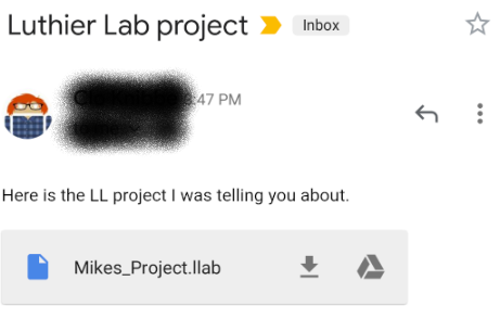
For example, suppose you receive an email with an attached LLAB file:

Press on the file name (in this example: Mikes_Project.llab), to import the file into Luthier Lab. The Import data dialog will appear, asking if you want to import the data.
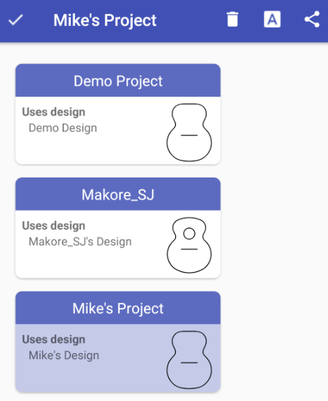
After you press on the button, Luthier Lab will import the data and open either the Design or Project Library depending on which kind of object (Design or Project) was in the file.
The newly imported Design/Project will be selected (in this example Mike’s Project is selected in the Project Library).
Import Collision
Name Collision
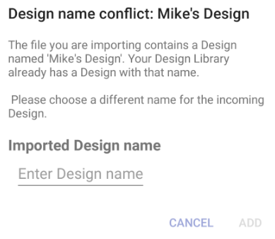
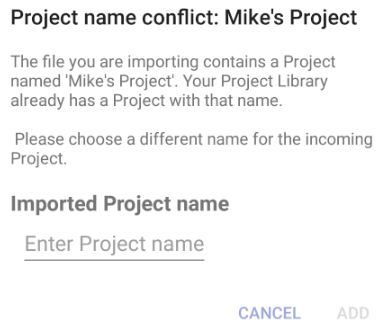
If you already have a Design/Project with the same name as the to-be-imported Design/Project, a dialog will appear giving you the option of canceling the import, or choosing a different name for the to-be-imported Design/Project.
If you are importing a Project, and there is a name collision for both the Project and the Design, the Design name conflict dialog will appear first, and then the Project name conflict dialog will appear. This gives you the opportunity to decide how you want to resolve each collision.
In this example, you are importing a project (Mike's Project), which contains the design Mike's Design, but you already have a project named Mike's Project and a design named Mike's Design. You can choose a different name for the Design and Project, or cancel each import.
Re-import Collision
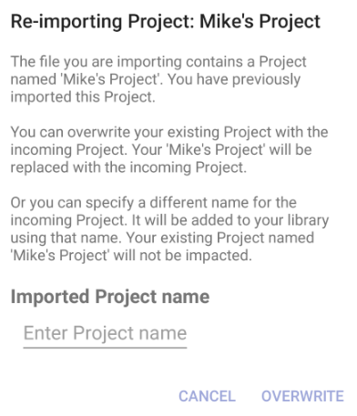
If you are importing a Design/Project that you had previously imported, the Re-importing collision dialog will appear to allow you to specify how to handle the collision.
Note: The Design/Project that you are re-importing may not be indentical to the previously imported copy, as you may have modified your copy, or the other Luthier Lab user may have modified their copy.
If you are re-importing a Project, the Re-importing Design dialog will appear first, and then the Re-importing Project dialog will appear. This gives you the opportunity to decide how you want to resolve each collision.
In this example, you are re-importing a project (Mike's Project), which contains the design Mike's Design. You can:
- Choose a different name for the Design and Project
- Overwrite your existing Design and Project
- Cancel each import

Settings
Bracing Patterns
- Show grid: If this switch is on: a grid overlay will be displayed.
- Snap to brace: If this switch is on: when drawing a brace, if one of its endpoints is near to another brace, the endpoint will snap to that brace.
Fretboard
-
Show saddle compensation: If this switch is on: the saddle
compensation will be displayed. See also: Fretboard.
Library
-
Make new project 'active': When a new project is added via the Project Library, it can be set as the active project.
This switch specifies the default setting of the checkbox on the Add project dialog.